

vPC Overview
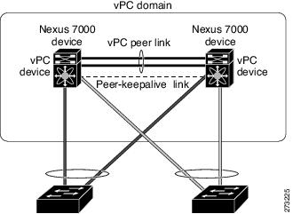
A virtual port channel (vPC) allows links that are physically connected to two different Cisco Nexus 7000 Series devices to appear as a single port channel by a third device (see Figure 7-1). The third device can be a switch, server, or any other networking device that supports port channels. A vPC can provide Layer 2 multipathing, which allows you to create redundancy and increase bisectional bandwidth by enabling multiple parallel paths between nodes and allowing load balancing traffic.
Figure 7-1 vPC Architecture
You can use only Layer 2 port channels in the vPC. A vPC domain is associated to a single VDC, so all vPC interfaces belonging to a given vPC domain must be defined in the same VDC. You must have a separate vPC peer link and peer-keepalive link infrastructure for each VDC deployed. Consolidating a vPC pair (two vPC peer devices of the same domain) in two VDCs of the same physical device is not supported. The vPC peer link must use 10-Gigabit Ethernet ports for both ends of the link or the link will not form.
You configure the port channels by using one of the following:
•![]() No protocol
No protocol
•![]() Link Aggregation Control Protocol (LACP)
Link Aggregation Control Protocol (LACP)
When you configure the port channels in a vPC—including the vPC peer link channel—without using LACP, each device can have up to 8 active links in a single port channel. When you configure the port channels in a vPC—including the vPC peer link channels—using LACP, each device can have 8 active links and 8 standby links in a single port channel. (See the “vPC Interactions with Other Features” section for more information on using LACP and vPCs.)

Note ![]() You must enable the vPC feature before you can configure or run the vPC functionality.
You must enable the vPC feature before you can configure or run the vPC functionality.
Beginning with Cisco NX-OS Release 4.2, the system automatically takes a checkpoint prior to disabling the feature, and you can roll back to this checkpoint. See the Cisco Nexus 7000 Series NX-OS System Management Configuration Guide, Release 5.x, for information on roll backs and checkpoints.
After you enable the vPC functionality, you create the peer-keepalive link, which sends heartbeat messages between the two vPC peer devices.
You can create a vPC peer link by configuring a port channel on one Cisco Nexus 7000 Series chassis by using two or more 10-Gigabit Ethernet ports in dedicated mode. To ensure that you have the correct hardware to enable and run vPC beginning with Cisco NX-OS Release 4.1(5), enter the show hardware feature-capability command. If you see an X across from vPC, your hardware cannot enable the vPC feature.
We recommend that you configure the vPC peer link Layer 2 port channels as trunks. Then, on another Cisco Nexus 7000 Series chassis, you configure another port channel again using two or more 10-Gigabit Ethernet ports in dedicated mode. Connecting these two port channels creates a vPC peer link in which the two linked Cisco Nexus devices appear as one device to a third device. The third device, or downstream device, can be a switch, server, or any other networking device that uses a regular port channel to connect to the vPC. If you are not using the correct module, the system displays an error message.
Note ![]() We recommend that you configure the vPC peer links on dedicated ports of different modules to reduce the possibility of a failure. For the best resiliency scenario, use at least two modules.
We recommend that you configure the vPC peer links on dedicated ports of different modules to reduce the possibility of a failure. For the best resiliency scenario, use at least two modules.
Beginning with Cisco NX-OS Release 4.2, if you must configure all the vPC peer links and core-facing interfaces on a single module, you should configure a track object that is associated with the Layer 3 link to the core and on all the links on the vPC peer link on both vPC peer devices. Once you configure this feature and if the primary vPC peer device fails, the system automatically suspends all the vPC links on the primary vPC peer device. This action forces all the vPC traffic to the secondary vPC peer device until the system stabilizes.
Create a track object and apply that object to all links on the primary vPC peer device that connect to the core and to the vPC peer link. See the Cisco Nexus 7000 Series NX-OS Unicast Routing Configuration Guide, Release 5.x, for information on the track interface command.
The vPC domain includes both vPC peer devices, the vPC peer-keepalive link, the vPC peer link, and all of the port channels in the vPC domain connected to the downstream device. You can have only one vPC domain ID on each device.
In this version, you can connect each downstream device to a single vPC domain ID using a single port channel.
Note ![]() Always attach all vPC devices using port channels to both vPC peer devices.
Always attach all vPC devices using port channels to both vPC peer devices.
A vPC (see Figure 7-2) provides the following benefits:
•![]() Allows a single device to use a port channel across two upstream devices
Allows a single device to use a port channel across two upstream devices
•![]() Eliminates Spanning Tree Protocol (STP) blocked ports
Eliminates Spanning Tree Protocol (STP) blocked ports
•![]() Provides a loop-free topology
Provides a loop-free topology
•![]() Uses all available uplink bandwidth
Uses all available uplink bandwidth
•![]() Provides fast convergence if either the link or a device fails
Provides fast convergence if either the link or a device fails
•![]() Provides link-level resiliency
Provides link-level resiliency
•![]() Assures high availability
Assures high availability
Figure 7-2 vPC Interfaces in One VDC

For more information on VDCs, see the Cisco Nexus 7000 Series NX-OS Virtual Device Context Configuration Guide, Release 5.x.
vPC Terminology
The terminology used in vPCs is as follows:
•![]() vPC—The combined port channel between the vPC peer devices and the downstream device.
vPC—The combined port channel between the vPC peer devices and the downstream device.
•![]() vPC peer device—One of a pair of devices that are connected with the special port channel known as the vPC peer link.
vPC peer device—One of a pair of devices that are connected with the special port channel known as the vPC peer link.
•![]() vPC peer link—The link used to synchronize states between the vPC peer devices. Both ends must be on 10-Gigabit Ethernet interfaces.
vPC peer link—The link used to synchronize states between the vPC peer devices. Both ends must be on 10-Gigabit Ethernet interfaces.
•![]() vPC member port—An interface that belongs to a vPC.
vPC member port—An interface that belongs to a vPC.
•![]() Host vPC port—A Fabric Extender host interfacesthat belongs to a vPC.
Host vPC port—A Fabric Extender host interfacesthat belongs to a vPC.
•![]() vPC domain—This domain includes both vPC peer devices, the vPC peer-keepalive link, and all of the port channels in the vPC connected to the downstream devices. It is also associated to the configuration mode that you must use to assign vPC global parameters.
vPC domain—This domain includes both vPC peer devices, the vPC peer-keepalive link, and all of the port channels in the vPC connected to the downstream devices. It is also associated to the configuration mode that you must use to assign vPC global parameters.
•![]() vPC peer-keepalive link—The peer-keepalive link monitors the vitality of a vPC peer Cisco Nexus 7000 Series device. The peer-keepalive link sends configurable, periodic keepalive messages between vPC peer devices.
vPC peer-keepalive link—The peer-keepalive link monitors the vitality of a vPC peer Cisco Nexus 7000 Series device. The peer-keepalive link sends configurable, periodic keepalive messages between vPC peer devices.
We recommend that you associate a peer-keepalive link to a separate VRF mapped to a Layer 3 interface in each vPC peer device. If you do not configure a separate VRF, the system uses the management VRF by default.
Source : cisco.com